Revcounter design
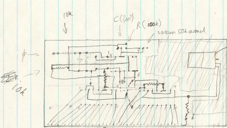
This circuit uses an LM2917 frequency to voltage converter. The input was connected to the low voltage side of the ignition coil, and the various components around it design to produce a full scale output at 6000rpm, which corresponds to 12000 ignition pulses per minute, or 200Hz. The voltage from this was then fed to 2 cascaded LM3914 bargraph drivers. I had 2 red LEDs for the top two segments, then 3 orange leds, and the rest were green. The "join" between two bargraph drivers was at 3000-3300rpm, which corresponded closely with the point at which the engine started to work well, so I set up the right-hand LEDs slightly brighter than the left hand ones. I etched a PCB (ahh the quality of the documentation!), using transfers for the pads and a pen for the lines, drilled the holes (with a snipped off paperclip for a drill bit) with a small plastic handdrill, and got soldering.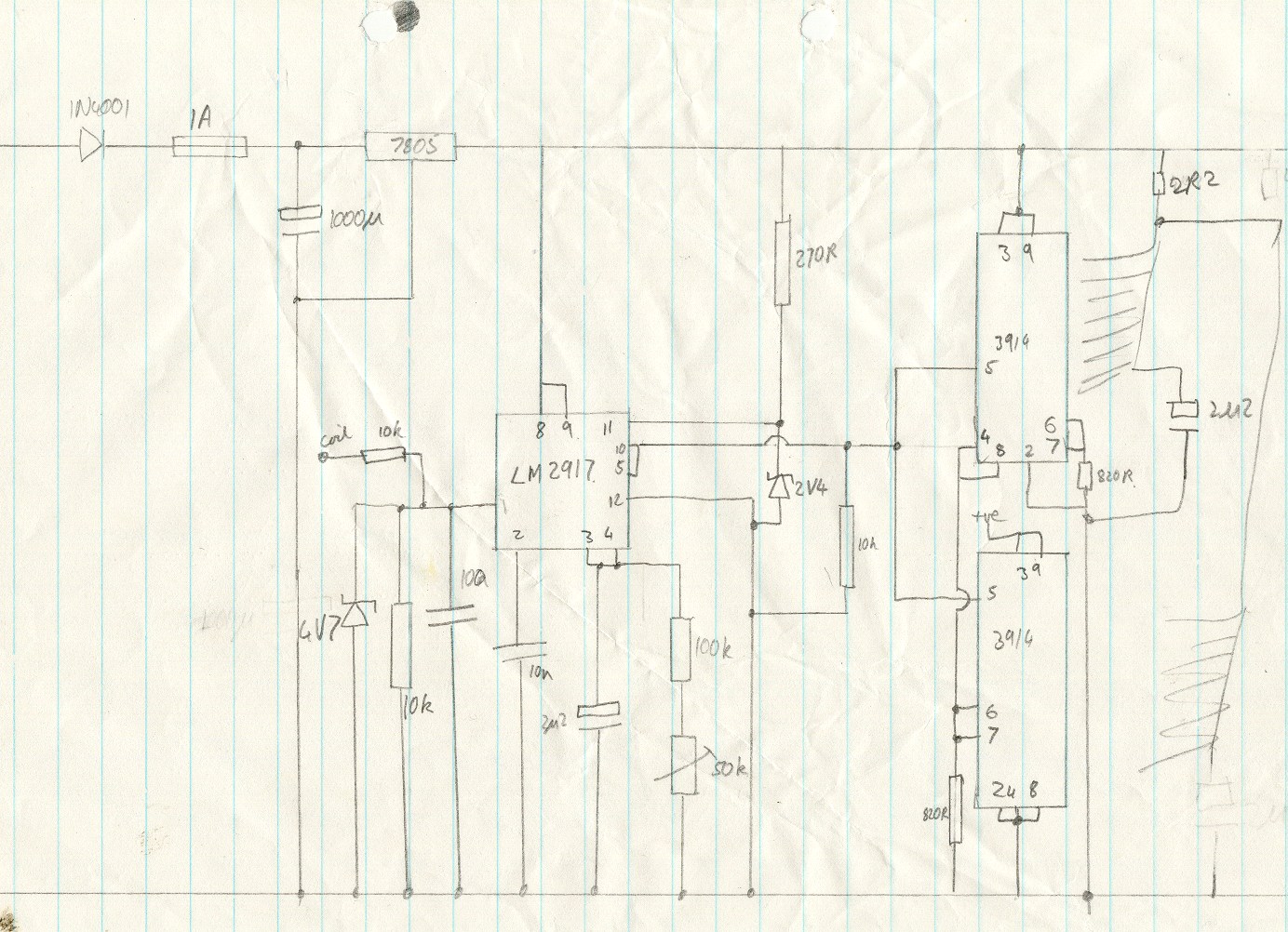
Tell me stuff
Last modified on 27th September 2006.
Compiled on Wed Apr 1 21:56:57 2009.
This page was created using my Webmaker software.
Valid code